There is a video with the transmission and perfect reception of the frequency set on the transmitter ELAD FDM-DUO (10) 489 618 400 Hz , the software SDR Console synchronized with the Beacon tall and active self calibration, it receives perfectly my transmitted signal of 10,489,618,400 Hz.
HOW TO SEE EXACTLY THE FREQUENCY OF TRANSMISSION TO THE SATELLITE OSCAR-100 WITHOUT CALCULATIONS AND WITH ABSOLUTE PRECISION ( +/- 0.0000000024 Hz).
SATELLITE RECEPTION FROM OSCAR 100 – SLIP OF THE FREQUENCY VALUE
Often we hear about the frequency shift when we listen to a station by Oscar-100 satellite, “The LNB for receiving satellite dish is slipping!” , OK, but it’s not the only problem that must be faced.
The solution for satellite reception Oscar 100, with any LNB and PLL, and not PLL (even with the cheapest LNB in the market without quartz) is resolved by the SDR Console software, with the LNB auto calibration , which It puts absolute remedy, and the frequency remains stable over time. An excerpt of my article on the topic:
How to enable the LNB auto calibration
With regard to the stability of the receipt of OSCAR 100 (no slippage of the reception frequency due to the LNB) the stability is ensured by the function SDR Console , (video of the undersigned, below) that hooks up to the frequency of Beacon high OSCAR 100 to 10,489 .800.000 Hz and automatically corrects the shift + or – (slippage) of the LNB frequency, maintaining the reception stable and perfect.
By adopting this solution, the problem of the LNB slipping will be resolved definitely in reception by Oscar 100 satellite.
SATELLITE TRANSMISSION TO THE OSCAR 100 – SLIP OF TRANSMISSION FREQUENCY
On any Transmitter (28-144-432 MHz) in SSB, USB mode, even the best quartz TCXO with 0.5 ppm (parts per million) of precisone, thermostat, has a tolerance of about a hundreds of hertz, of slip frequency. In the conversion circuit of the signal to be sent Oscar 100, the signal from the transmitter, arrives to the Upconverter that increases the output of up to 2,400,000,000 Hz, which is 2.4 GHz and the few hundred hertz become thousands. In addition to this, we need to add the slippage also of the Upconverter, which has its own internal oscillator (TCXO with quartz with 0.5 parts per million, in the best of cases) and we are completely out of frequency with respect to the frequency of the satellite frequency on which to transmit.
Another dilemma is that of having to make the rate calculation, to be set on the transmitter, to have a certain output frequency to the satellite, here’s the Band Plan with Down-link , the RX frequency and the ‘ UP-Link : 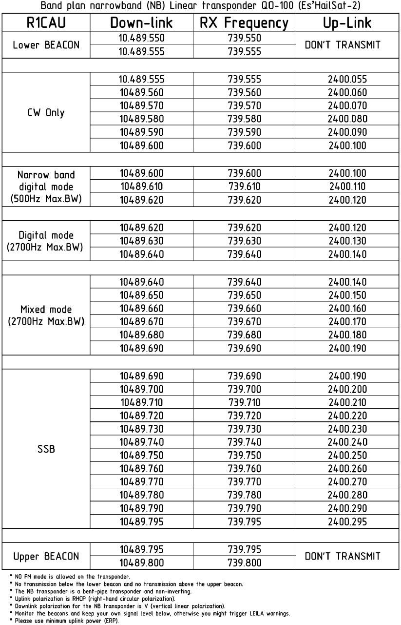 Sample calculation. I send a 144 290 Mhz, the frequency output from the up converter, will be 2400.290 MHz which corresponds to the actual output frequency from transponder Down-link totaled 10489790.000 MHz. But if I have to transmit on the frequency of 10489790.550 MHz , what will be the frequency that I will set the transmitter? How many Hertz do I have to move up or down in frequency to launch my QSO request to colleagues who talk on satellite?
From the QSO I did on Oscar 100 and that I listen to, many colleagues who have used the solution to receive the QO-100 satellite, radio directly on the apparatus, with a LNB that brings frequeza receiving in the same band transmission, continue making QSOs off frequency (1 / 1.5 kHz up or down), because they do not realize it since they do not have a reference frequency. Many use another method, which is to ritual, that is, to hold for a time the transceiver is on so reaching temperature the transmission frequency is more stable and then through WebSDR networked control the transmission frequency and store the corrections to be made to be closer to the precise frequency of transmission (example: adding 507 Hertz to the transmission frequency I will be closer to the real one sendig back to the transponder Down-link).
SATELLITE TRANSMISSION TO THE OSCAR 100 – ABSOLUTE ACCURACY OF TRANSMISSION FREQUENCY – THE SOLUTION
I USED MY FDM-DUO FOR THE ULTIMATE SOLUTION TO VARIOUS ISSUES RELATED TO SATELLITE TRANSMISSION TO THE OSCAR 100.
Now I will explain the solution I have adopted for a transmission to the Oscar-100 satellite, which completely simplifies all the problems described above, and that at the time of writing (August 2019) to my knowledge no one has made.
The solution is to use an GPSDO synchronized with the Rubidium atomic clocks of the GPS satellites, which generates a signal at 10 MHz that synchronizes the transmitter, replacing the internal TCXO quartz to 0.5 ppm and the same signal will be used from the Upconverter replacing its local oscillator TCXO and to engage the 10 MHz of frequency GPS referenced to 10 MHz.
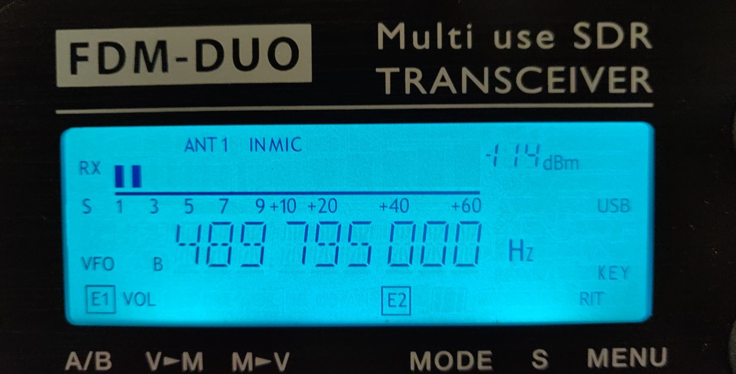
The transceiver apparatus ELAD FDM-DUO has the possibility with an SMA input, to use an external 10 MHz clock, GPS referenced , for the transmission and reception and it is also possible to activate an offset on the frequency of transmission in such a way that it is displays the exact frequency that we are going to transmit to the satellite, without calculations or adjustments of any kind.
 The FDM-DUO represented above will transmit exactly on (10) 489 795 000 Hz without any necessary correction and with an error ( +/- 0.0000000024 Hz) very accurate, so even if you want to transmit (10) 489 796. 777 Hz, just adjust the tuning and press the PTT, easy and without any calculation to be performed.
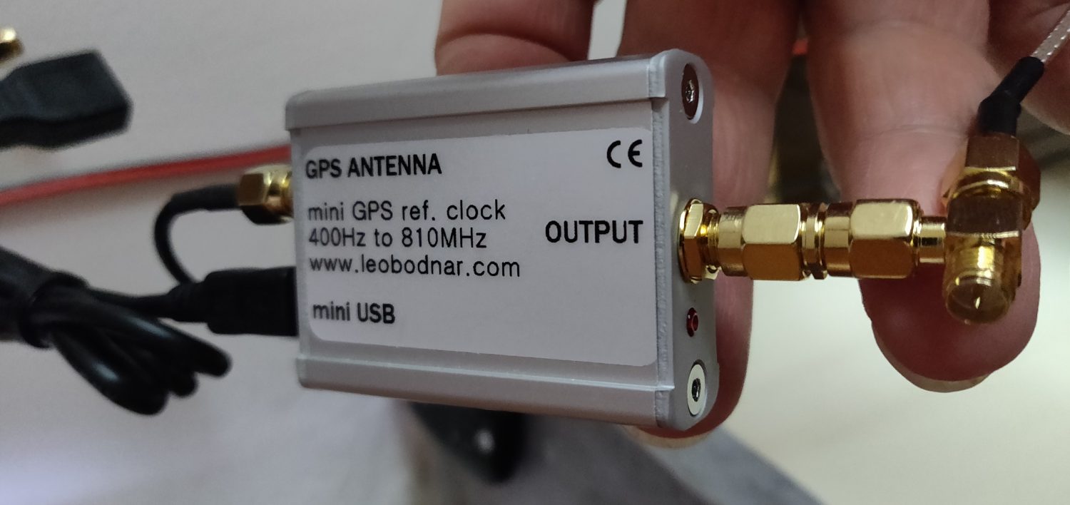
Now follow in detail the settings required to perform on ‘FDM-DUO to activate the Offset, which will display the exact frequency of transmission and connection to the GPSDO Leo Bodnard ( LINK ) that needs an attenuator of 6 dBm on signal at 10 MHz for driving correctly the input of ‘FDM-DUO, which requires an input signal equal to 0 dBm. I also changed the settings of Leo Bodnard GPSDO, bringing the 10 MHz signal output + 6.4dBm, 8mA drive setting, using the supplied software.
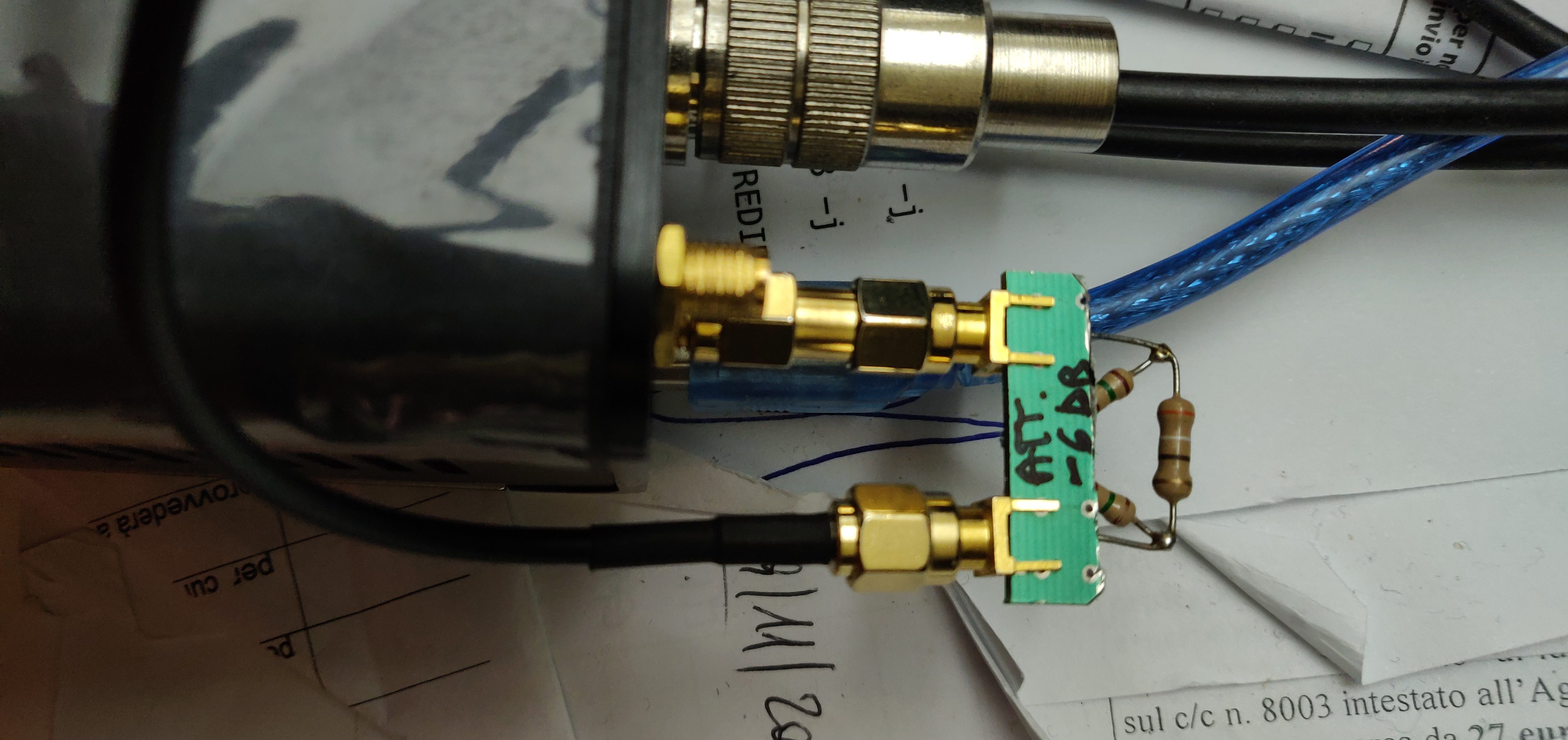
 attenuator Construction:
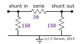
input impedance 51 Ω [swr: 1.0]
output impedance 51 Ω [swr: 1.0]
Attenuation 6.1 dB
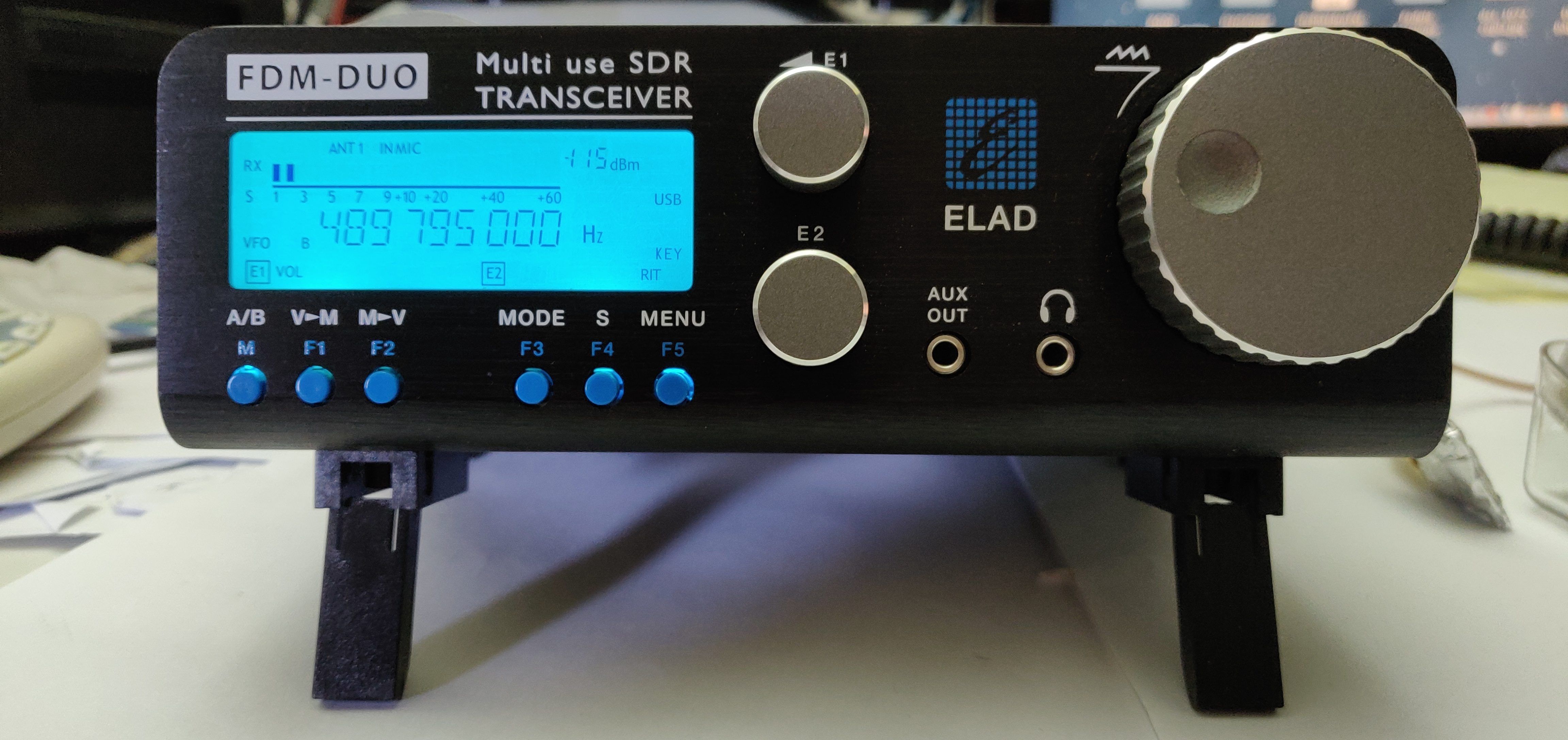
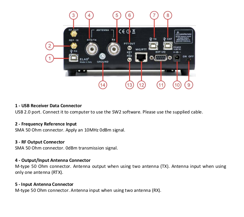
 Turn off the FDM-DUO, enable GPSDO to 10 MHz, wait until it lines up on the GPS satellites (30 sec max) and turn the FDM-DUO on, if the input signal level aL REF IN (item 2 of the photos below ) is correct will light up on the display REF iN (under the written H z), which indicates that the clock to the transmitter arrives from the GPS referenced at 10 MHz.
 Given that the transmitter will work on the 28 MHz and also the ‘ Upconverter of DX Patrol MK2 , it has to be set up for that frequency, we will see now the configurations to run on’ FDM-DUO . DX Patrol upconverter MK2. Set S1 to the frequency of 28 MHz.
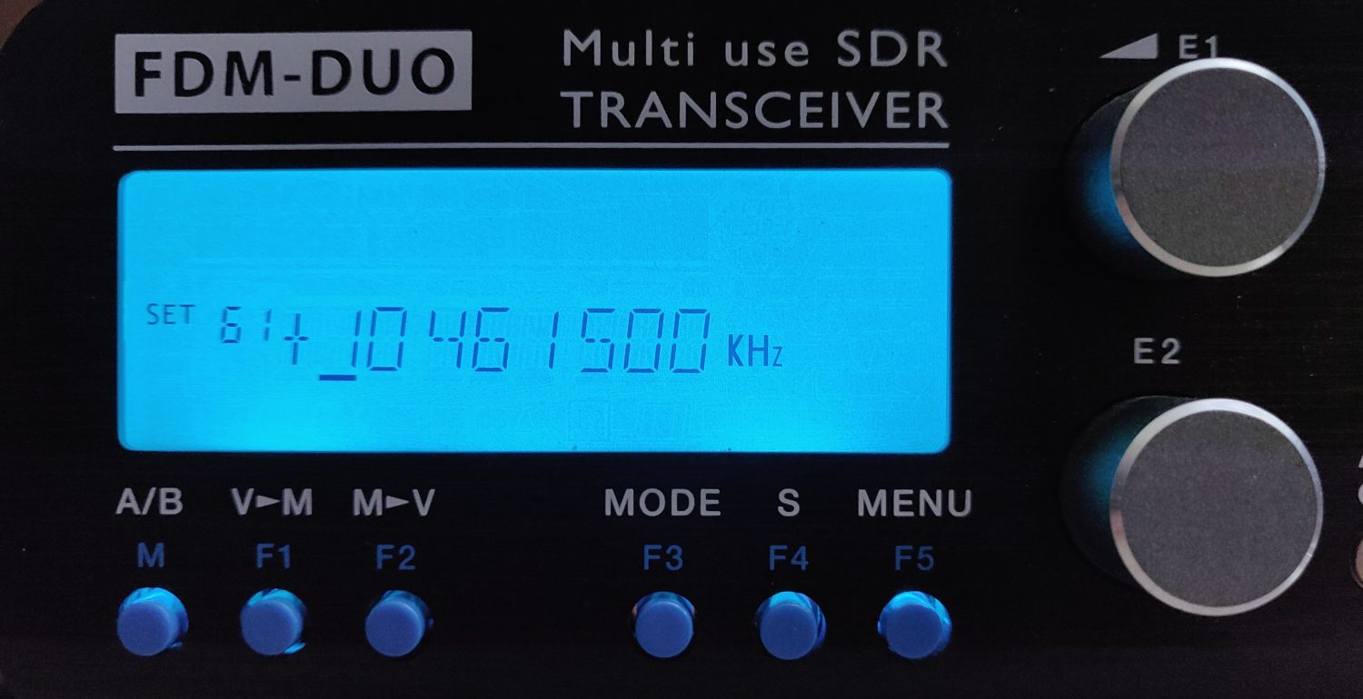
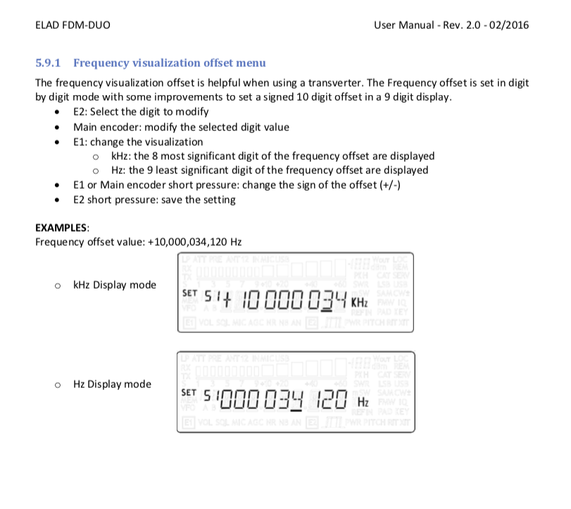
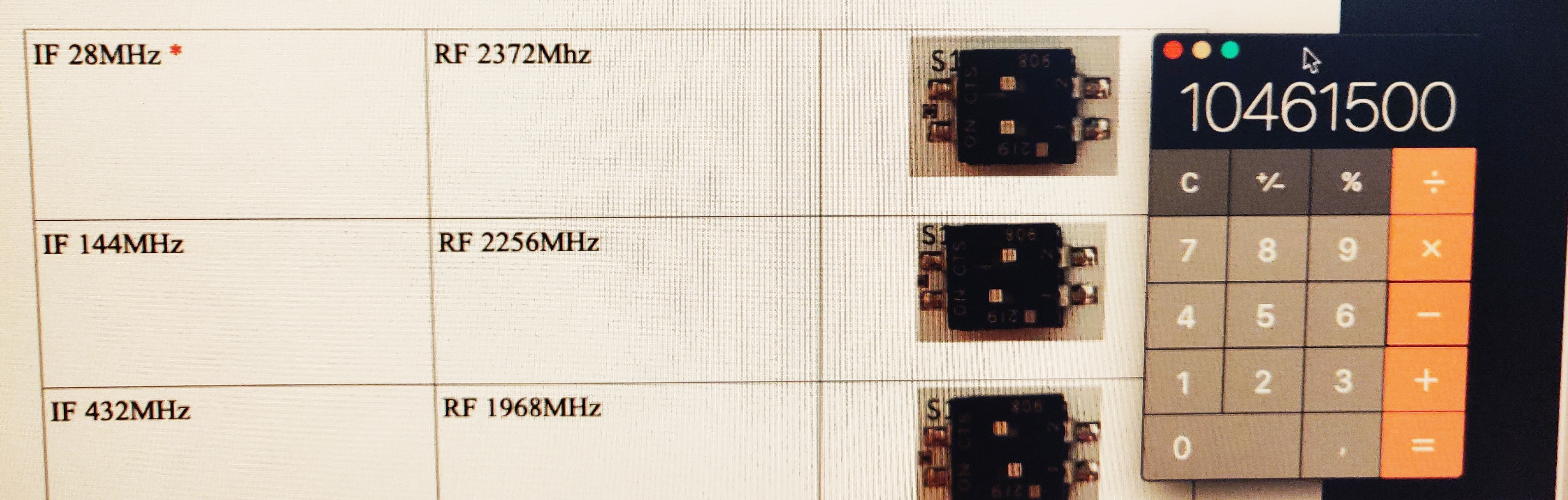 From the menu, select settings of the apparatus ( 61 ) OFS VALUE and insert the offset value equal to 10.4615 billion , (for example, to determine the value to be inserted 10469690-28190 = 10.4615 million KHz offset value). Under the settings and the manual page dell’FDM-DUO dedicated to the offset configuration.
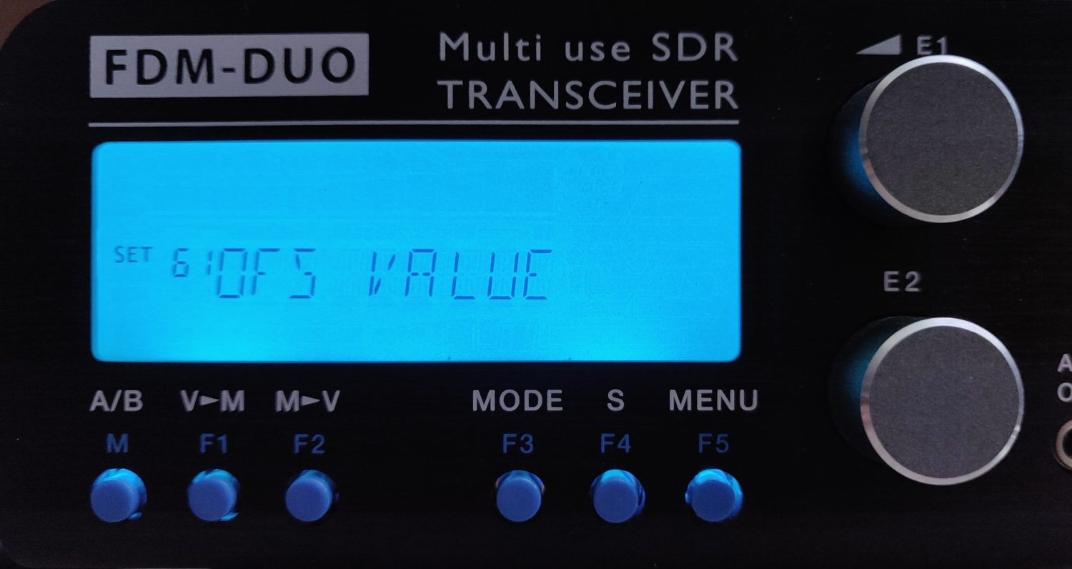
Below there is a video with the transmission and perfect reception of the frequency set on the transmitter ELAD FDM-DUO (10) 489 618 400 Hz , the software SDR Console synchronized with the Beacon tall and active self calibration, it receives perfectly my transmitted signal of 10,489,618,400 Hz.
Good mid-August and have fun with experimentation, which keeps alive the interest in radio, as did the dear Marconi throughout his life and has given us this technological innovation that has changed the world.
73 by Antonio IU8CRI.
Related Video:
MIA SPERIMENTAZIONE – Oscar 100 – Trasmettere e ricevere facilmente e con il minimo della spesa